Introduction
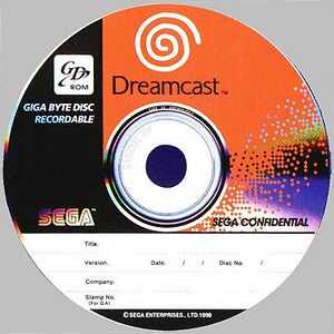
Welcome to the Sega Naomi-GD-Rom-System ROMs section of the ROM Database. Please scroll down for more sections and remember to share this page. You can also vote for your favourite system. Sega Naomi DIMM board and GD-ROM. From Arcade Otaku Wiki. Jump to: navigation, search. The Naomi DIMM has a 3 wire battery pack consisting of small PCB and 2 x Panasonic CGR18650H cells. The H is probably some rating, I used CGR18650CF's which have a bit better capacity. Sega Naomi GD-ROM Service Manual. The NAOMI arcade-board features 168 MB of solid-state ROMs or GD-ROMs using a custom DIMM board and GD-ROM drive. In operation, the Naomi GD-ROM is read only once at system powerup, downloading the disc's contents to the DIMM-Board RAM. Once the download is complete, the game executes out of RAM, thereby reducing mechanical wear on the GD-ROM. SEGA NAOMI GD-ROM HARDWARE [ BACK TO MAIN PAGE] - [ SEGA HARDWARE PAGE]. GD Rom system has a very clever way of getting around the loading delay time. When the game is initially installed, the GD ROM loads its content into the Naomi RAM. Once this is completed, the GD ROM goes into standby unless the RAM gets corupted or the game gets shut.
Sega Naomi Gd Rom
This guide details how to replace a failed GD-ROM drive with a new working drive.
Sega Naomi Roms Torrent

Be sure to replace the GD-ROM with one corresponding to your model number. Refer to the Top Cover Disassembly Guide for instructions on where to find your model number.
Problem with this guide: The photos incorrectly show the power supply has been removed.
No parts specified.
Verify that the console is disconnected from the AC outlet before you begin.
Flip the console over on its back.
Take note of your model number, in case replacement parts are needed.
Remove the expansion bay by applying pressure to the small clip on the expansion bay while prying it away from the console.
Locate and remove all four black 12mm Phillips #02 screws from the underside of the console.
Note: Remove the expansion bay to locate the fourth screw
Internal components can be loose. Be careful that they do not fall out when removing the cover.
Turn the console right side up.
Remove the top cover by gently lifting the upper portion of the console.
Detach the orange cable by giving it a gentle pull while wiggling the cable back and forth until it loosens from the logic board.
Detach the cables by gently pulling the three GD-ROM cables to remove them from the logic board.
Remove the two black 12mm Philips #02 screws located on the left side of the GD-ROM bracket.
The console is rotated 90 degrees counter-clockwise in the first photo. The second photo depicts the normal position.
When lifting the GD-ROM, be careful that the top half of the casing does not detached from its base.
Remove the GD-ROM by gently lifting it from its base.
Replace the bad GD-ROM drive with a functional one.
Secure the new GD-ROM drive to the console with the Philips #2 screws.
Connect the three GD-ROM cables to the logic board.
Connect the GD-ROM data ribbon to the logic board.
6 other people completed this guide.


Embed this guide
Choose a size and copy the code below to embed this guide as a small widget on your site / forum.